
- Home/
- Products/
- 4th Axis Rotary Tables/
- Worm Gear Rotary Table/
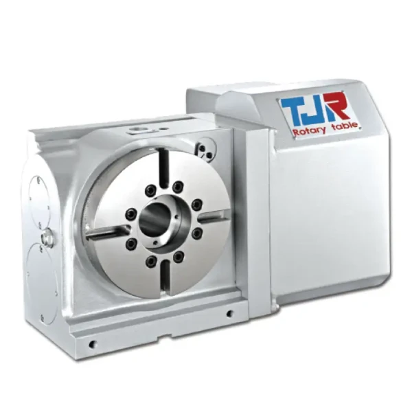
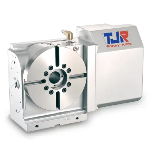
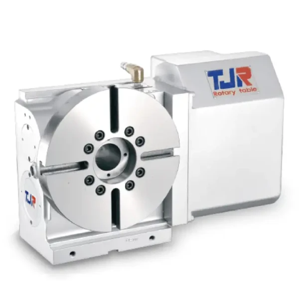
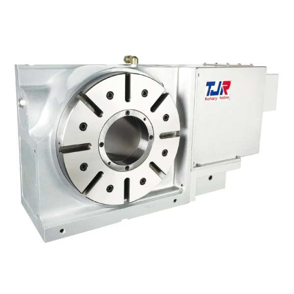
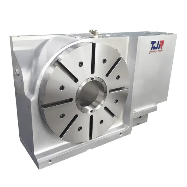
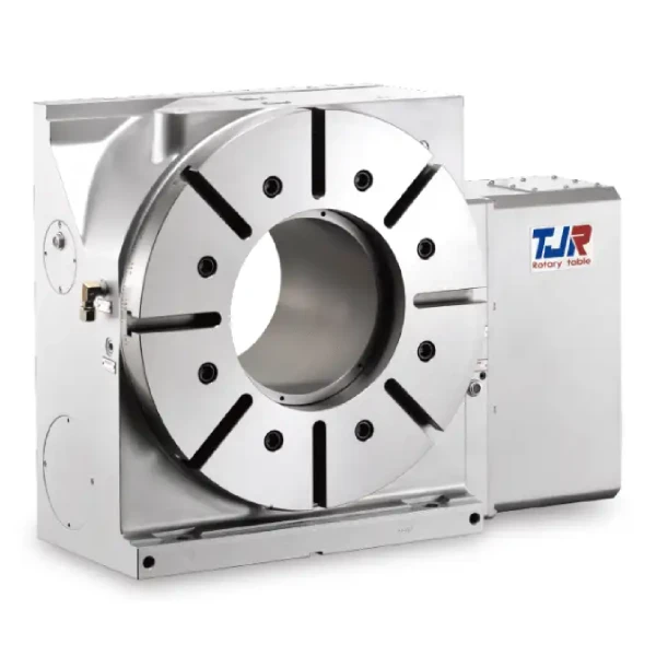
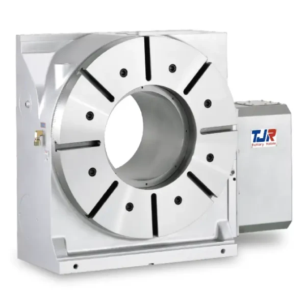
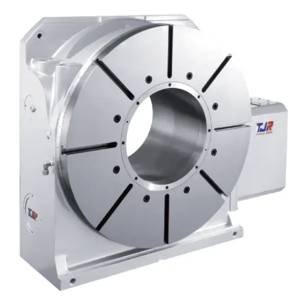
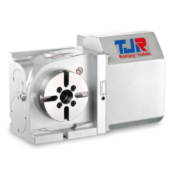
- TJR Worm Gear Rotary Table - AR Ø255
TJR Worm Gear Rotary Table - AR Ø255
Smooth seamless transmission with high reduction ratios for precision loads.
AR-255RH
AR-255RH Product Specifications
| Item | Data |
|---|---|
| Application | Vertical and Horizontal |
| Installation Mode | Add-on |
| Table diameter(mm) | Ø255 |
| Inner diameter of mandrel sleeve(mm) | Ø80H7 |
| Diameter of center through hole(mm) | Ø80 |
| Center height (Vertical)(mm) | 160 |
| Table height (Horizontal)(mm) | 200 |
| Table T-slot width(mm) | 12H7 |
| Guide block width(mm) | 18h7 |
| Transmission Mechanisms | Worm and Worm Gear |
| Min. increment(deg.) | 0.001 |
| Indexing precision(sec.) | 15 |
| Repeatability(sec.) | 6 |
| Clamping system (MPa / kg/cm²) | Pneumatic (0.6 / 6) |
| Clamping torque(N.m / kgf · m) | 687 / 70 |
| Servo motor model(FANUC)(Straight shaft without key) | αiF8 / βis12 |
| Servo motor model(MITSUBISHI) (Straight shaft without key) | HG - 154 |
| Speed reduction ratio | 1 / 120 |
| Max. rotation rate of table(min-1) | 33.3 |
| Allowable inertia load capacity (vertical)(kg-m²) | 1.2 |
| Allowable workpiece load (Vertical)(kg) | 100 |
| Allowable workpiece load (with support table)(kg) | 250 |
| Allowable workpiece load (Horizontal)(kg) | 250 |
| Allowable thrust load (with rotary table clamping) F (N / kgf) | 19620 / 2000 |
| (Axial)*1 Allowable thrust load (with rotary table clamping) FxL (N.m / kgf·m) | 1472 / 150 |
| (Radial)*2 Allowable thrust load (with rotary table clamping) FxL (N.m / kgf·m) | 687 / 70 |
| Driving torque(N.m / kgf·m) | 540 / 55 |
| Net weight ( sever motor excluded)(kg) | 118 |
| *1 | If a mechanical brake is not used, this value will correspond to the motor's holding torque. |
| *2 | The structural limit value, while the actual operating speed will vary depending on the motor. |
AR-255HN Product Specifications
| Item | Data |
|---|---|
| Application | Vertical and Horizontal |
| Installation Mode | Add-on |
| Table diameter(mm) | Ø255 |
| Inner diameter of mandrel sleeve(mm) | Ø80H7 |
| Diameter of center through hole(mm) | Ø80 |
| Center height (Vertical)(mm) | 160 |
| Table T-slot width(mm) | 12H7 |
| Guide block width(mm) | 18h7 |
| Transmission Mechanisms | Worm and Worm Gear |
| Min. increment(deg.) | 0.001 |
| Indexing precision(sec.) | 15 |
| Repeatability(sec.) | 6 |
| Clamping system (MPa / kg/cm²) | Pneumatic (0.6 / 6) |
| Clamping torque(N.m / kgf · m) | 687 / 70 |
| Servo motor model(FANUC)(Straight shaft without key) | αiF8 / βis12 |
| Servo motor model(MITSUBISHI) (Straight shaft without key) | HG - 154 |
| Speed reduction ratio | 1 / 120 |
| Max. rotation rate of table(min-1) | 33.3 |
| Allowable inertia load capacity (vertical)(kg-m²) | 1.2 |
| Allowable workpiece load (Vertical)(kg) | 100 |
| Allowable workpiece load (with support table)(kg) | 250 |
| Allowable thrust load (with rotary table clamping) F (N / kgf) | 19620 / 2000 |
| (Axial)*1 Allowable thrust load (with rotary table clamping) FxL (N.m / kgf·m) | 1472 / 150 |
| (Radial)*2 Allowable thrust load (with rotary table clamping) FxL (N.m / kgf·m) | 687 / 70 |
| Driving torque(N.m / kgf·m) | 540 / 55 |
| Net weight ( sever motor excluded)(kg) | 118 |
| *1 | If a mechanical brake is not used, this value will correspond to the motor's holding torque. |
| *2 | The structural limit value, while the actual operating speed will vary depending on the motor. |
HR-255R Product Specifications
| Item | Data |
|---|---|
| Application | Vertical or Horizontal |
| Installation Mode | Add-on |
| Table diameter(mm) | Ø255 |
| Inner diameter of mandrel sleeve(mm) | Ø80H7 |
| Diameter of center through hole(mm) | Ø80 |
| Center height (Vertical)(mm) | 160 |
| Table height (Horizontal)(mm) | 200 |
| Table T-slot width(mm) | 12H7 |
| Guide block width(mm) | 18h7 |
| Transmission Mechanisms | Worm and Worm Gear |
| Min. increment(deg.) | 0.001 |
| Indexing precision(sec.) | 15 |
| Repeatability(sec.) | 6 |
| Clamping system (MPa / kg/cm²) | Hydraulic (3.5 / 35) |
| Clamping torque(N.m / kgf · m) | 687 / 70 |
| Servo motor model(FANUC)(Straight shaft without key) | αiF8 / βis12 |
| Servo motor model(MITSUBISHI) (Straight shaft without key) | HG - 154 |
| Speed reduction ratio | 1:120 |
| Max. rotation rate of table(min-1) | 33.3 |
| Allowable inertia load capacity (vertical)(kg-m²) | 1.2 |
| Allowable workpiece load (Vertical)(kg) | 100 |
| Allowable workpiece load (with support table)(kg) | 250 |
| Allowable workpiece load (Horizontal)(kg) | 250 |
| Allowable thrust load (with rotary table clamping) F (N / kgf) | 19620 / 2000 |
| (Axial)*1 Allowable thrust load (with rotary table clamping) FxL (N.m / kgf·m) | 1472 / 150 |
| (Radial)*2 Allowable thrust load (with rotary table clamping) FxL (N.m / kgf·m) | 687 / 70 |
| Driving torque(N.m / kgf·m) | 540 / 55 |
| Net weight ( sever motor excluded)(kg) | 109 |
| *1 | If a mechanical brake is not used, this value will correspond to the motor's holding torque. |
| *2 | The structural limit value, while the actual operating speed will vary depending on the motor. |
HR-255G Product Specifications
| Item | Data |
|---|---|
| Application | Vertical or Horizontal |
| Installation Mode | Add-on |
| Table diameter(mm) | Ø255 |
| Inner diameter of mandrel sleeve(mm) | Ø80H7 |
| Diameter of center through hole(mm) | Ø80 |
| Center height (Vertical)(mm) | 190 |
| Table height (Horizontal)(mm) | 200 |
| Table T-slot width(mm) | 12H7 |
| Guide block width(mm) | 18h7 |
| Transmission Mechanisms | Worm and Worm Gear |
| Min. increment(deg.) | 0.001 |
| Indexing precision(sec.) | 15 |
| Repeatability(sec.) | 6 |
| Clamping system (MPa / kg/cm²) | Hydraulic (3.5 / 35) |
| Clamping torque(N.m / kgf · m) | 687 / 70 |
| Servo motor model(FANUC)(Straight shaft without key) | αiF8 / βis12 |
| Servo motor model(MITSUBISHI) (Straight shaft without key) | HG - 154 |
| Speed reduction ratio | 1:120 |
| Max. rotation rate of table(min-1) | 33.3 |
| Allowable inertia load capacity (vertical)(kg-m²) | 1.2 |
| Allowable workpiece load (Vertical)(kg) | 100 |
| Allowable workpiece load (with support table)(kg) | 250 |
| Allowable workpiece load (Horizontal)(kg) | 250 |
| Allowable thrust load (with rotary table clamping) F (N / kgf) | 19620 / 2000 |
| (Axial)*1 Allowable thrust load (with rotary table clamping) FxL (N.m / kgf·m) | 1472 / 150 |
| (Radial)*2 Allowable thrust load (with rotary table clamping) FxL (N.m / kgf·m) | 687 / 70 |
| Driving torque(N.m / kgf·m) | 540 / 55 |
| Net weight ( sever motor excluded)(kg) | 115 |
| *1 | If a mechanical brake is not used, this value will correspond to the motor's holding torque. |
| *2 | The structural limit value, while the actual operating speed will vary depending on the motor. |
HR-255N Product Specifications
| Item | Data |
|---|---|
| Application | Vertical or Horizontal |
| Installation Mode | Add-on |
| Table diameter(mm) | Ø255 |
| Inner diameter of mandrel sleeve(mm) | Ø80H7 |
| Diameter of center through hole(mm) | Ø80 |
| Center height (Vertical)(mm) | 160 |
| Table T-slot width(mm) | 12H7 |
| Guide block width(mm) | 18h7 |
| Transmission Mechanisms | Worm and Worm Gear |
| Min. increment(deg.) | 0.001 |
| Indexing precision(sec.) | 15 |
| Repeatability(sec.) | 6 |
| Clamping system (MPa / kg/cm²) | Hydraulic (3.5 / 35) |
| Clamping torque(N.m / kgf · m) | 687 / 70 |
| Servo motor model(FANUC)(Straight shaft without key) | αiF8 / βis12 |
| Servo motor model(MITSUBISHI) (Straight shaft without key) | HG - 154 |
| Speed reduction ratio | 1:120 |
| Max. rotation rate of table(min-1) | 33.3 |
| Allowable inertia load capacity (vertical)(kg-m²) | 1.2 |
| Allowable workpiece load (Vertical)(kg) | 100 |
| Allowable workpiece load (with support table)(kg) | 250 |
| Allowable thrust load (with rotary table clamping) F (N / kgf) | 19620 / 2000 |
| (Axial)*1 Allowable thrust load (with rotary table clamping) FxL (N.m / kgf·m) | 1472 / 150 |
| (Radial)*2 Allowable thrust load (with rotary table clamping) FxL (N.m / kgf·m) | 687 / 70 |
| Driving torque(N.m / kgf·m) | 540 / 55 |
| Net weight ( sever motor excluded)(kg) | 109 |
| *1 | If a mechanical brake is not used, this value will correspond to the motor's holding torque. |
| *2 | The structural limit value, while the actual operating speed will vary depending on the motor. |
Request a Quote
Tell us about your requirements, and we will develop a tailored solution for you
Download Digital Product Catalogue
Download the brochure and see what precision looks like.
Built on Innovation and engineered for Excellence.
We deliver precision indexing and rotary solutions that meet the highest standards of performance, trusted by manufacturers who demand accuracy, reliability, and results at every stage of production.